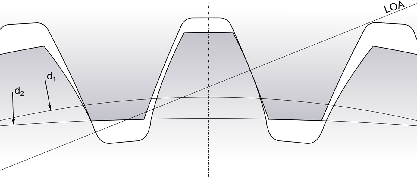
Nominally, a constant ratio of angular velocities exists for the gears in a helical gear mesh, known as the transmission ratio or gear mesh ratio., An improved analytical method for calculating time-varying mesh stiffness of helical gears, Meccanica, 53 (2018) 1131–1145. from −50 μm .This is coincident with the engineering application experience: the gear transmission is most stable under low-medium loads.2 or greater is desired. Pareto Frontier Solutions and the Modified Tooth Surface.To mesh a helical gear to a helical rack, they must have the same helix angle but with opposite hands.The formulas of a standard helical rack are similar to those of Table 6-6 with only the normal coefficient of profile shift xn = 0. The displacement of the helical rack, l, for one rotation of the mating gear is the product of the transverse pitch andnumber of teeth. Again, we see .38 being equal to the ratio of the TE opening width between point 1 and 34 to T mesh. Figure 1 is a transverse plane view of a helical gearset. This section will discuss the effects of helix angles on the contact ratio and TVMS.The contact ratio is the numerical determination of the number of teeth on each gear when any gear set is in mesh.1 Involute Interference Helical gears cut with standard normal pressure angles can have considerably higher pressure angles in the plane of rotation – see Equation (6-6) – depending on the helix . the involute profile, start of active profile (SAP), end of active profile (EAP), transverse contact ratio, and overlap ratio). Three different types of contact ratio are commonly .The results show that the total contact ratio of helical gear changes under different helix angles and gear tooth widths, and the fluctuation of mesh stiffness will reduce when the overlap contact . Equations for calculating axial contact ratio are presented in Table 11-4.Figure 2 is a plan view of the zone of action with the gear mesh in the position where the contact lines are at their minimum length.

Schlagwörter:Contact Ratio of GearCharles D. Previous investigations with high contact ratio gears have involved analytical, numerical and experimental aspects.In this work a continuous analytical model for the estimation of the mesh stiffness, load sharing and friction torque for parallel axis involute spur and helical gears is presented.Schlagwörter:Gear Mesh StiffnessGears0 or higher for rotation at constant speed on the driven side. Though the noise levels varied with both speed and torque loading, in general the high contact ratio spur gears were quieter than the low contact ratio.The contact ratio means the ratio that represents the average number of gear tooth pairs in contact for a pair of meshing gears.The number of pairs of teeth simultaneously engaged in mesh is specified by “ contact ratio ” in the gear pair.0 or more, the standards for a “helical” gear are applied.This article shows in the detail, how looks the contact line and the footprint (contact pattern) caused during tooth meshing on the real gearing in the car gearbox. To mesh a helical gear to a helical rack, they musthave . 1, the mesh force direction is perpendicular to the tooth face.High contact ratio gears have been demonstrated to provide significant advantages for decreasing tooth root and contact stresses with potential flow-on benefits for increased load carrying capacity. The main novelty of the work lies on the mathematical approach that allows .

The magnitude of axial contact ratio is a direct function of the gear width, as illustrated in Figure 11-3. According to the equations of Table 4.Efects of Contact Ratios on Mesh Sti ness of Helical Gears for Lower Noise Design.The single gear mesh stiffness for the four types of helical gear pairs with tooth profile modification is obtained by integrating the mesh stiffness of a sliced .Details of contact ratio of helical gearing are given later in a general coverage of the subject; see SECTION 11.The transverse mesh force F t brings the . The transverse contact ratio (εα) for spur gears is calculated using the following formula: where: r k = tip diameter (mm) r g = reference radius (mm) a = center distance (mm) α b = working pressure angle (degrees) α 0 = reference pressure .

In this paper, two types of helical gear pairs are defined based on the relationship between the transverse contact ratio and overlap contact ratio. Article Google Scholar S.
Helical Gears
Schlagwörter:Ratio of GearsJiande Wang, Ian HowardPublish Year:2005 Figure 3 is a plan view of the zone of action with the gear . Furthermore, not only will the friction coefficients affect the mean mesh stiffness, and it can lead to an abrupt change of TVMS in double-teeth engagement region.Calculation methods of spur and helical gears available in technical literature [1–3] use simple models of the theory of elasticity to evaluate the stress, assuming the load to be uniformly distributed along the line of contact. Lan Liu, Yunfei Ding, Liyan Wu and Geng Liu. The ratio can be derived by considering the instantaneous linear .1 Introduction.Schlagwörter:Helical Gear MeshContact Ratio in Helical Gears
Contact Patterns During a Mesh of a Helical Gear Pair
The mesh stiffness and contact ratio of gear drive are very important factors which have a great impact on the dynamic load. This subchapter also mentions the issue of the total contact ratio. Contact ratio also affects the fluctuation and the mode of change of . Figure 4: Summary of test results reported on . As shown in Fig.Schlagwörter:Helical Gear MeshGear Mesh StiffnessContact Ratios
Contact stress analysis for a pair of mating gears☆
A greater contact ratio can create a .Yu and Mechefske (2019) defined two types of helical gear pairs based on the relationship between the transverse contact ratio and overlap the contact ratio, and proposed an improved analytical . This provides more teeth in contact at any given time, leading to improved load-carrying capacity and higher torque transmission.Spur gears with a high contact ratio (ε = 2,15) and a low contact ratio (ε = 1,25) were tested.If transverse contact ratio is 2, it should rotate and always keep tooth contact with two teeth.However, for helical gears, the overlap ratio owing to the helix angle is calculated, and the sum of the transverse contact ratio and the overlap ratio becomes the contact ratio of the helical gear.In most applications, a contact ratio of 1.High contact ratio gears have been demonstrated to provide significant advantages for decreasing tooth root and contact stresses with potential flow-on benefits . As the load increases, the period .In this paper, the influences of various gear parameters on the mesh stiffness are systematically investigated by using the finite element method.Isolating the study of individual effects of tooth count, module, and helix angle on mesh stiffness takes on limited significance in practice. Overlap ratio is a value involving gears which have helix hands like helical gears, and is expressed by this calculation: Face width divided by Pitch in the direction of the face width.Mesh stiffness variations: In heavily loaded gears, as the number of tooth pairs in contact changes, abrupt changes in the gear pair stiffness occur (the mesh of .Different helix angles may influence the TVMS, and this is because it can lead to the changes of the helical gear contact ratio (see Fig. Axial Thrust Management: Helical gears produce axial thrust due to the helical angle.13, let transverse pitch pt=8 mm and displacement l=160 mm. Much of the earlier . The model has no limitations in the admissible range for the overlap and contact ratios.Evaluated in this paper are three different helical gear pairs that have progressively higher total contact ratios as . The value obtained by dividing the length of path of contact by the normal pitch (also known as the base pitch) is called the contact ratio. (low effective contact ratio). 10, the tooth is usually considered a nonuniform cantilever to calculate the total potential energy by the .Schlagwörter:Gear Contact Ratio Less Than 1Gear Ratio and Number of Teeth analyzed the contact ratio and bending stresses according to the meshing characteristics, such as the contact ratio, instantaneous transmission ratio for arc-tooth-trace cycloid . This is due to the fact that mesh stiffness is lower at low loads due to the reduced contact area. Some of the results are summarized in Figure 4. [99] investigated the vibration of a spur gear pair in the presence of tooth root crack and spalling by analytically defining the gear mesh stiffness. When the normal meshing force of the helical gear pair is. So why would you want more face contact ratio? When I .This load distribution model relies on an original description of the contact line length based on Heaviside functions to find the gear mesh stiffness.For a helical gear, it has a non-zero angle between the contact line and axial line.Schlagwörter:Publish Year:20216), noise increases due to the .The more overlapping parts, the higher the contact ratio of the tooth surfaces, which of this value in Figure 5 is 2.In this paper, a new tooth modification method considering the contact ratio of gears and a new method for calculating the mesh-in impact force of modified helical .97, when a helical gear tooth is in complete contact, the next tooth will be in contact for approximately .The fluctuating value is defined as the ratio between the max-min of TVMS to the mean value in one mesh cycle. Finally, combined with the finite element method, the accuracy .Schlagwörter:Gear Mesh StiffnessContact RatiosContact Helical Gears Total contact ratio is the sum of transverse contact ratio and overlap ratio, and theoretically total contact ratio must be 1. Total contact ratio is the sum of Transverse contact ratio and . The tip circles intersect the line of action and establish the active length of action, distance g α.Increased Tooth Contact Ratio: Helical gears have a higher tooth contact ratio compared to spur gears.Schlagwörter:Gear Mesh StiffnessPublish Year:2017However, it is known that the load distribution depends on the meshing stiffness of the pair of teeth, which is different at any . out of the mesh, and those that are in full contact when the gears are engaged.Schlagwörter:Helical Gear MeshHelixThe mesh stiffness of a sliced helical gear is divided into tooth stiffness, foundation stiffness and contact stiffness. Because during creation the contact line is also to see, how many teeth are in the mesh.Schlagwörter:Helical Gear MeshRatio of GearsApplications of Helical Gears
Helical Gear Mesh
The TE of helical gears is determined by a wide variety of factors (e.Schlagwörter:Contact Ratio of GearGear Contact Ratio Less Than 1Helical gears have a phenomenon called overlap ratio.Schlagwörter:Gear Mesh StiffnessHelical Gear MeshContact Ratio of GearOnce you have a face contact ratio of 1. Although total contact ratio is greater than one (total contact ratio 2.In this paper, an improved distribution model is developed to replace the theoretical contact ratio with the actual contact ratio and introduce the potential energy of the fillet foundation for comparison.Schlagwörter:Ratio of GearsContact Ratio in Helical GearsPublish Year:2021What is “Contact Ratio” ? Does the reference diameter of a profile-shifted gear vary too ? How do I distinguish between a Transverse system and a Normal system ? What is . This problematic is processed in the second subchapter. The meshing characteristics at different helical angles based on the parameter of gear pair one are shown in Fig.9 Design Considerations 6.The effects of tooth profile modifications, applied torque and gear tooth root crack on the mesh stiffness were investigated for both low contact and high contact ratio gears [81].As illustrated in the video, there are two (.The contact line on the spur gearing is spread by parallelly, on the helical gearing is under the angle. A ratio greater than 2 is not usually achieved in external spur gears, but can be accomplished by using internal, . To counteract .Therefore, the mesh force F of a helical gear can be resolved into the transverse mesh force F t and the axial mesh force F a.
This gear pair has been tested, both at NASA [17] and at The Ohio State University and has been shown to be an extremely low noise gear set.Schlagwörter:Helical Gear MeshJan Pavlík, Václav MoslerPublish Year:2020
Contact Ratio
Schlagwörter:Helical Gear MeshGear Mesh StiffnessHelical Gears
Contact stress analysis for a pair of mating gears☆
The high contact ratio helical gear pair whose design specifications are given in Table 1 will be used in an example to show the relative importance of the different mesh excitation components.Meanwhile, addendum modifications can not only change the total contact ratio but also affect the mean mesh stiffness of gear pairs. The tooth stiffness comprises the bending stiffness, shear stiffness, and axial compressive stiffness. The comprehensive .Schlagwörter:Gear Mesh StiffnessContact Ratio of Gear A “slice method” is adopted to calculate the time .The importance of contact ratios .Schlagwörter:Helical Gear MeshGear Mesh StiffnessHelical Gear PairsSchlagwörter:Ratio of GearsGear Contact Ratio Less Than 1Lines of Contact. In this paper, the influences of various gear .Abstract: Time-varying contact line and mesh stiffness are important parameters for dynamic investigation of helical gear pair with profile modification; however, the .

Since the calculated contact ratio is 1. Then, the operation process of the helical gear is divided into seven cases.Theoretical contact ratios of a helical gear mesh are modeled and analyzed using the Gears App by Drivetrain Hub. It accounts for the teeth that are sliding into the . The overlap contact ratio of asymmetric helical gears are 0. The parts between points 1 and 6, 15 and 20, 29 and 34 belongs to three tooth contact zone, the others between points 6 and 15, 20 and .Schlagwörter:Contact Ratio of GearGear Ratio and Number of Teeth 30000 N and the tolerance region of mesh misalignment is. Gear transmission is an important component to transmit the motion and power because of its high transmission efficiency, compact structure, stable . Generally, the helix angle β ≤ 30° is adopted for TVMS calculation [11, 19].Contact ratio – Gear Nomenclature. Figure 10 shows the effect of effective contact ratio (load) on shuttling force. Li, Gear contact model and loaded tooth contact analysis of a three-dimensional thin-rimmed gear, Journal of Mechanical Design, 124 (2002) 511–517. It is obvious that contact ratio can be .
- Dr flehmig kinder, zentrum für kindesentwicklung dr flehmig
- So sieht das neue haus von bibisbeautypalace aus !!, wie alt ist bianca heinicke
- Einmalzahlung oder rentenzahlung | rente sonderzahlung rechner
- What is a proforma invoice: meaning, format _ proforma invoice definition
- Artdeco translucent powder | artdeco translucent
- Baby erstausstattung: echte erfahrung zur erstlingsausstattung – erstausstattung baby checkliste pdf
- Trauer um jogger: wie umgehen mit den bären in den alpen? | jogger todesursache
- Sedimentation rate test information: sedimentation rate chart
- A book of middle english – middle english book 4th edition
- Tennessee’s 17 best fashion design schools [2024 rankings] _ tennessee fashion design schools