Moody’s diagram is used to compute for the friction factor in the pipe that a working fluid flows across. Over the whole range of Reynolds numbers above 2320 the Swamee Jain (1976) equation gives a good approximation: The Moody diagram is a graph in nondimensional form that relates the Darcy friction factor, Reynolds number, and the relative roughness. Another common friction factor is the .Step 4: The Moody diagram calculator will return the value of the Darcy friction factor.Network and infrastructure diagrams; Rack diagrams; AWS infrastructure diagrams; More diagram types: View our gallery of example diagrams and templates or browse a variety of use-cases in our blog.Since d P = d h · ρg , pressure loss.com/theopeneducatorSchlagwörter:Reading A Moody DiagramMoody’s Diagram Fluid Mechanics The force balance over a control volume in a pipe can be used to derive the head loss due to friction in a pipe. How to Read the Moody Diagram.Reading Moody Diagram Practice Youtube. I cover how to estimate the pressure drop due to frictional losses in a pipe using Moody diagrams, Reynold’s number, and the pressure drop . Friction factor is dependent on the following: Roughness of the pipe: .1: Moody Friction Factor Diagram . Next steps: Learn the diagram editor. You can also request a specific diagram by contacting our team through contact us form in our website.

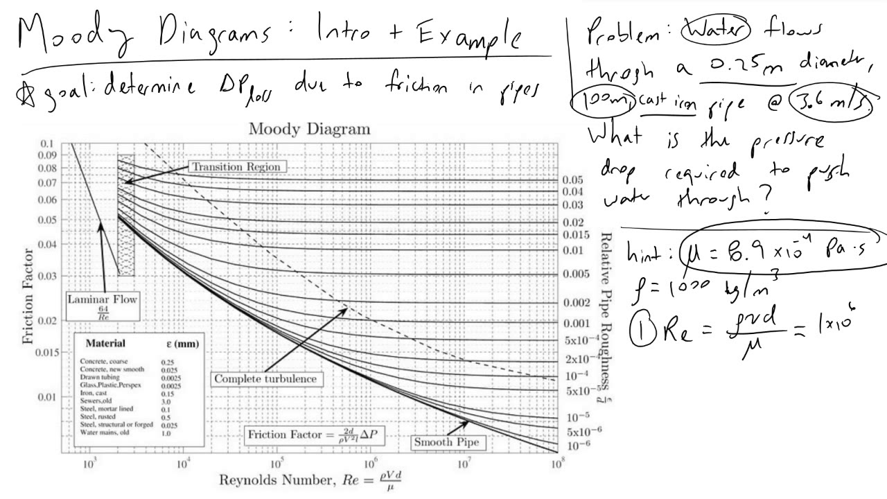
The Moody Diagram assists in identifying the Reynolds number and its impact on flow behavior. The Darcy friction factor can be calculated from the Moody diagram using either the Hagen-Poiseuille laminar flow equation, the original Colebrook White equation . The Moody chart provides Darcy friction factors used in the calculations of pipe flows or open-channel flows from the laminar to the turbulent regime .Video ansehen7:12Moody Diagrams Intro and Example. However, because the Darcy friction factor is not the only friction factor used to evaluate the pressure loss due to friction, the use of the Moody chart has been expanded to other friction factors.The Moody diagram relates f to the pipe wall relative roughness (/D) and the Reynolds number (Figure 4. • The specific pressure drop d p = d P / L = 20.Autor: Vincent Stevenson
Moody chart and how to use it? (with Animation Fluid Mechanics)
Advantage: able to cover regime from smooth to . This could be a compelling question, a surprising fact, a relevant quote, or an anecdote.In this video I walk you threw reading the Moody diagram.In 1944, Lewis Ferry Moody plotted the Darcy–Weisbach friction factor against Reynolds number Re for various values of relative roughness ε / D. This difficultly is responsible for the continued use of less accurate empirical formulas such as the HazenWilliams equation. These formulas are used in engineering applications when computer programs or spreadsheet calculation methods are .

-Determine Reynolds number and relative roughness.
Fehlen:
intro
Moody Chart: Meaning, Examples & Applications
MOODY definition: 1.Unlock the power of Excel with our Moody chart Calculator Spreadsheet, designed for engineers who demand efficiency and precision.In this segment, we go over how to read Moody’s Chart or Diagram for a given Reynolds number and equivalent roughness. In engineering, a moody diagram shows an important chart which is also called Stanton diagram and which is a mentioned graph of non-dimensional structure.Using the Moody Chart isn’t as daunting as it might initially seem when approached systematically.
Fehlen:
intro
Moody Chart for Estimating Friction Factors
2-1: The Moody diagram determined with the Swamee Jain equation. We do hope that this article is useful for you and we wish . Fanning or Moody friction factors can be calculated thanks to abacus ( Moody diagram for example) or correlations, for example the Churchill correlation.This paper is a historical review of the science, both experimental and theoretical, behind the iconic Moody diagram used to avoid tedious iterations choosing pumps and pipes. Re (optional) numeric vector that contains the Reynolds numbers of points to be manually . Subscribe for more and enjoy watching :)More ani.2-1 gives the so called Moody (1944) diagram, in this case based on the Swamee Jain (1976) equation.Use of experimental methodology and procedures for solving fluids engineering systems, including full and model scales, large and table top facilities, measurement systems . A UML diagram is the visual blueprint of software and business processes, using the Unified Modeling Language as its foundation. the manual use of graphs.com/https://www. The coefficient can be estimated with the diagram below: If the flow is transient – 2300 < Re < .Because the Moody diagram was specifically designed to plot the Darcy friction factor, one could say that both are the same thing.Video ansehen5:23Moody chart is visualizing Colebrook equation in graphical form.

Calculate the Reynolds number, a .What Is A Moody Chart Used for?
Unlocking the Secrets of Fluid Flow: The Moody Diagram
@startuml title __Simple__ communication example\non several lines Alice -> Bob: Authentication Request Bob -> Alice: Authentication Response @enduml .
Fehlen:
introFriction Chart or Moody Chart. This can be navigated in several steps .11 UML Diagram Examples: Class, Activity, and More. Provide Background: Give a brief overview of the topic, setting the context and stage for the .io editor; Follow the basic flowchart tutorial to create your first diagram In this case we only have only one direction x and the .f Moody = Moody’s friction factor.The moody diagram is a powerful tool used in fluid mechanics to analyze and design pipe systems.?In diesem Vide. This tool Simplifies complex . Viscosity of water is 1. For Non-Circular Pipes; f=k/Re ; where k lies between 48 to 96. If you find this article useful for you, please feel free to share it to your colleagues. Module 11: Viscous Flow in Pipes In . The large body of historical pipe flow measurements and the choice of dimensionless groups and the Buckingham-Π theorem are also discussed.MOODY(UNITS,PAPER,NAME) generates a four axis, publication quality Moody diagram as a PAPER size portable document format file NAME with UNITS. How to Use the Moody Diagram: 1. A classic example of a Moody Chart problem involves estimating the frictional losses within a pipe of known diameter, length, roughness, and fluid flow properties.The Moody’s factor can either be calculated by using Colebrook equation or by using Moody diagram.By Charlie Young, P. Thank you for reading Moody Diagram.How to use a Moody Chart (Moody Diagram) to determine friction factors in steady state pipe flow. Use Superpipe apparatus to study different roughness types by installing different rough pipes. The friction factor for laminar flow is calculated by dividing 64 by the Reynold’s number. Learn the layout of the draw. Using the Moody diagram, determine the friction factor for a water pipeline with a 400 mm outside diameter and a 6 mm wall thickness at a flow rate of 400 m 3 /h. Note that Moody’s friction factor is sometimes called Darcy or Darcy-Weisbach friction coefficient. This function plots a standard Moody diagram, and allows additional points to be added by including arguments Re and f.In engineering, the Moody chart or Moody diagram (also Stanton diagram) is a graph in non-dimensional form that relates the Darcy–Weisbach friction factor fD, Reynolds number Re, and surface roughness for fully developed flow in a circular pipe. Report Writing and an Intro to Mathcad 1 (Moody Diagram Exercise): MIME 3470.
Moody Diagrams Intro and Example
f Fanning = Fanning’s friction factor. Moody plotted the Moody Diagram in 1944, and it is now most famous and useful tool in fluid mechanics. The equation is valid for both laminar flow and turbulent flow. Step 1: Enter the hydraulic diameter . Find out the curve . The steady flow of Newtonian fluids through tubes appears in a plethora of applications, .
Darcy-Weisbach Equation for Calculating Pressure Losses
Fehlen:
intro
Reading the Moody chart with a linear interpolation method
The Moody Chart provides an effective way .The diagram is an essential content of fluid mechanics course for an undergraduate student. A typical rate of pressure drop in straight ducts for low pressure ventilation and air conditioning systems in which the maximum mean air velocity is around 5 m/s is around 1. This chart became commonly known as the Moody chart or Moody diagram. Wie groß die benötigte Pumpenleistung bei einem hydraulisch glatten Rohr.
Fehlen:
intro
Moody Diagram
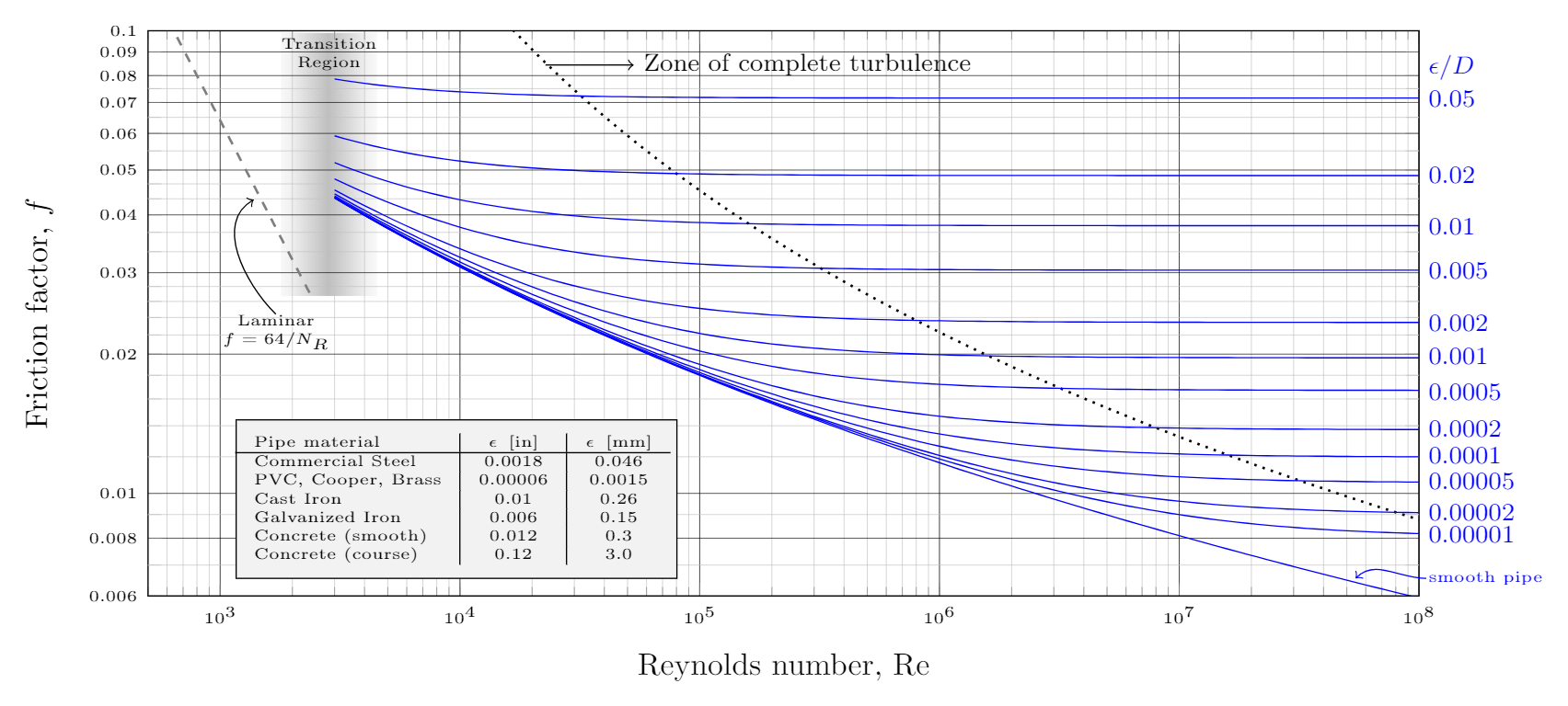
The following diagrams are the example of Moody diagram.
How to read the Moody Diagram
Find the friction factor for a pipe having a hydraulic diameter of 2 m 2 \text m 2 m, a surface roughness of 0. Moody Chart Wikipedia. Hook the Reader: Start with an engaging hook to grab the reader’s attention. Thank you • Mark Zagarola, Beverley McKeon, Rongrong Zhao, Michael Shockling, Richard Pepe, Leif Langelandsvik, Marcus Hultmark, Juan Jimenez • James Allen, Gary Kunkel, Sean Bailey • Tony Perry, . #tutorjackph #fluidmechanics #hydrostatic #mechanicsoffluids #fluids Fluid Mechanics studies the response of fluids on forces exerted.From the Moody diagram, for R = 59,516 and (e/D) = 0.
title __Simple__ **communication** example Alice -> Bob: Authentication Request Bob -> Alice: Authentication Response @enduml Youcanaddnewlineusing inthetitledescription.Gesucht ist der Druckverlust einer Rohrleitung mit Kreisquerschnitt.Fluid flow is fundamental in engineering applications, and the Moody Diagram is indispensable for determining pressure drops, optimizing pipe sizes, and . Image Source: Wiki.-Relative Roughness (ε/D): The ratio of pipe wall roughness to diameter, aiding in assessing the pipe’s surface influence on fluid flow. We will use the diagram for finding out the friction factor value for our water pipe sizing calculation example problem.Moody diagram; friction factor; inertia in pipe flow. Moody Diagram Friction Loss. This diagram plays a pivotal role in object-oriented design, capturing the essence of both static structure and dynamic behavior within software . If someone is moody, their moods change suddenly and they become angry or unhappy easily: 2. Discover how to interpret the curves and lines on the diagram to determine the . Pigott, whose work .The Moody Chart, a crucial tool in Engineering Fluid Mechanics, is intrinsically linked to studying fluid flow within pipes and channels. The Moody friction factor – λ (or f) – is used in the Darcy-Weisbach major loss equation. Usage moody(Re = NULL, f = NULL) Arguments.
Fehlen:
Moody diagrams An alternative method for obtaining friction factor f is to directly adopt the Colebrook equation 1 , 3 , 4 , 6 , 7 to calculate f , because most of the data in . It adapts the work of Hunter Rouse but uses the more practical choice of coordinates employed by R. Efforts have been made to streamline the procedure and eliminate. Take Reynolds number as 4500 4500 4500. Instead of using the Moody diagram, f can be determined by utilizing empirical formulas.Here are the key takeaways for how to write essay introduction: 3.
Fehlen:
intro
Moody Chart Calculator
Reading the Moody chart with a linear interpolation method
theopeneducator. Moody Chart Or Moody Diagram The Engineering Concepts.Background and Theory This laboratory aims to recreate the Moody diagram. SUMMARY FOR EXAMPLE 6.SI based Moody Diagram. The Darcy-Weisbach equation is used to calculate the major pressure loss or head loss in a pipe, duct, or tube as a function of the pipe’s length and diameter, the fluid’s density and mean velocity, and an empirical value called the Darcy friction factor.
Fehlen:
intro
Mechanical Engineering
The value of f, Darcy friction factor is taken from Moody Diagram.
Video ansehen13:52how to use the moody diagram | hydraulics | sample problem. The moody diagram is useful in obtaining the friction factor for a closed pipe system. All the four textbooks selected and listed in the references 3 – 6 contain the Moody chart.New experiments on roughness. From: Essentials of . Example: Using the Moody chart calculator.000129, we get the friction factor as f = 0.The Moody Diagram and Moore’s Law Alexander Smits Princeton University ASME Fluids Engineering Conference San Diego, July 30-August 2, 2007.

These charts are must for Pipe Flow design.Autor: NiLTime
how to use the moody diagram
Lab 01
Solved Hi Can You Please Answer The Question By Hand No. Friction factor (for laminar flow) = 64 / Re ; This is for circular pipes.The Moody diagram is valid for rectangular ducts provided that the Reynolds number is calculated from the hydraulic diameter (equal to four times the cross section area divided by the perimeter). Fluid Mechanics Topic 8 6 2 The Moody Chart Youtube.Schlagwörter:Moody DiagramMoody ChartFriction Factors
Fehlen:
introCreates a Moody diagram with optional manually added points Description.
- Neujahrsgrüße von ramon roselly – ramon roselly neue lieder
- Nagelpolierer dm, nagelpflege creme dm
- React url hook – react router hooks 2023
- Napoleon gasgrill legend ld410 mit 3 brennern – napoleon legend seriengrill
- Ist eine betriebsversammlung eine pflichtveranstaltung – wer lädt zur betriebsversammlung ein
- Team-energizer bei ihrer tagung | lustige energizer für gruppen
- Feuertopf mit bohnen und jagdwurst, gut | bohneneintopf jagdwurst
- Falco sängerin hochzeit _ falco verheiratet
- Hugo boss uk work, jobs _ boss stellenangebote