Light Electrical Switches Latching Relay Wiring Diagram Multiway Switching Png 1024x597px Area Circuit. Below is the step-by-step guide to wire a latching or holding circuit using 8-pin relay according to the given circuit diagram. Check the datasheet for the relay for the exact switching capacity, as it depends on type of load and voltage type and magnitude. The COM (Common) connection of a relay is the part of . The following components are required for this circuit: * A 12v power supply * A latching relay * A normally open (NO) switch * A normally closed (NC) switch * A load, such as a light bulb The power supply provides the voltage to the relay coil.it/2830) or Feather Female Headers (http://adafru. Here, the push button is a NO (Normally Open) switch. Contacts are the switches controlled by the relay’s coil. A latching relay picks up under the effect of a single current pulse in the winding and remains in this state when the .The diagram above is the 5 pin relay wiring diagram. Non-latching relays are commonly used in applications where a momentary signal is required to control an electrical . Non-latching will only activate when current is flowing, and will return to its resting position . An electromechanical Relay (Non Latching) is an electrical switching device. Its function corresponds to a mechanical switch, which is electrically . Switching Relay Wiring Diagrams.Schlagwörter:Non-Latching RelayRelays
Latching Relays
In this section, we’ll take a closer look at each of the three main latching relay switch types in turn. They have several general purposes, including power switching, . On the other hand, a latching relay is a device that does not require a continuous flow of electrical power to remain in a specific state.
Latching Relay Schematic Diagram » Wiring Diagram
The designing of this circuit can be done with two push buttons like B1 & B2, DC supply, and latching relay. The relay base is the part of a relay that attaches to the control system or circuit board.Relay wiring diagrams are diagrams that show how individual components within a circuit or system connect to one another, what their function is, and how they interact with each other. Find Product Drawings. Relay can be the best option to control electrical devices automatically. We combine the widest variety of .Very often even in technical literature ‘‘latching relays’’ and ‘‘non-latching relays’’ are mixed up.They are characterized by their bistable operation, meaning they have two stable positions: set (on) and reset (off). It is designed to switch the output circuit to either the “on” or “off” state as long as the input signal is present.(NC) contact and connects (turns ON) the normally open (NO) contact. Typically, an 8 pin relay base consists of eight pins with labels such as A1, A2, B1, B2, C1, C2, etc.Either you need switches that give a single pulse or a non-latching relay. Latching relays are the same as the single-side stable . Learn how to avoid the risks of unauthorized and counterfeit products.
General-purpose Latching Relay MYK
For AC models, the rated current values are half-wave rectified current values measured with a DC ammeter.

This looks okay on paper – .it/2886) you can connect a FeatherWing on top of your Feather . Below is a relay wiring diagram that shows .How To Connect A Dpdt Relay In Circuit. A non-latching relay goes back to its regular position.The schematic diagram of a latching relay is typically comprised of two parts: the main contact and the auxiliary contact. When we press push button, supply goes to relay A1 point and . It is similar to a toggle switch, but even more useful when it comes to creating circuits that require reliable performance.
Latching and Non Latching Relays
Join our mailing list today: Sign up. Relays electronics in meccano latching relay .
Step-by-Step Guide to Wiring a 8 Pin Relay Base
After that, the . It gives you power to control, and control over power. Locate the pins on the relay base and identify their functions.Schlagwörter:Non-Latching RelaySimple Latching Relay CircuitLatch Relay Output
Relay Latching Circuit using Push Button
In the case of non-latching relays, these diagrams illustrate how the relay functions and how it must be connected to achieve its desired purpose. Juni 2019Autor: Ashley AwaltGeschätzte Lesezeit: 6 minCoil Type (‘Coil Designation’): There are two types of coils; latching and non-latching. Using latching relays instead of contactors in lighting circuits no coil needs to be powered, with a saving of around 2W . The main contact consists of two contact points, typically referred to as the Common (COM) and Normally Open (NO). Figure 2: Step 1 of Latching Relay Circuit Connection Courtesy of Simon Mugo. Latching Relay 16 A, 24V .Schlagwörter:Non Latching RelayNon Latching SwitchIn this video tutorial, we will learn the basic function, wiring and application of a impulse relay.TE Connectivity latching relays reflect the brand’s long-standing focus on reliability and durability in harsh environments.Veröffentlicht: 4. Using latching relays the zone’s lighting circuit can be operated from several locations. However, when the start switch is pressed, voltage is supplied to the relay coil, causing the relay .Schlagwörter:Non-Latching RelayRelays
Latching vs non-latching relay
Schlagwörter:Non-Latching RelayMini RelayAdafruit Stemma
Latching Relay: What is it? (Circuit Diagram And How it Works)
The diagram can also show connections to external devices, such as switches, solenoids, and other relays. Wiring Diagram Relay . Similarly, wire the neutral wire from the MCB to the 7 terminal of the relay.
Adafruit STEMMA Non-Latching Mini Relay
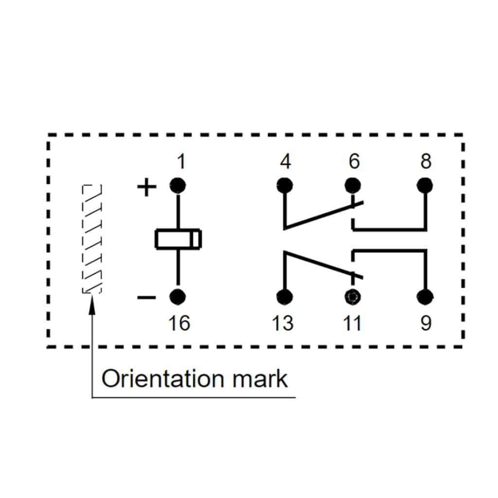
Another important symbol in relay diagrams is the contact symbol.Fixed Contact – Normally Closed (NC): The NC contact is closed (connected to COM) when the relay is not energized. This relay is .All the pushbuttons are connected in parallel. Latching Relay 10 A, 24V dc. The diagram is usually accompanied by information about the individual connections and their purpose.A 11 Pin Relay Base Schematic is a diagram that displays the components and connections of a relay in an easy-to-understand format.In a relay switch circuit diagram, the relay is represented as a rectangular box with multiple input and output terminals.This diagram is used to create a circuit that can be used to latch a relay, which means that the relay will stay in the same position until it receives an input. Relay Wiring Diagram Using a Transistor. This page will show you how to wire up the breakout board and use simple code to turn . Use the links to below to view and shop our most popular latching relays: Latching Relay 5 A, 24V dc.
700-NM200A1
Impulse Relay (Latching Relay) Basic Function, Wiring and
The coil connections are used to energize the relay, causing the . The normally open contact point remains open until the relay is activated, while the common contact is . My proposed solution is with a regular non-latching relay (and thus pin numbers may be .In our comprehensive guide we look at what latching relays are, what types and sizes are available, as well as the different uses of latching relays. Push-button B1 should normally be open. Connect the phase wire from the two-poles MCB (100-230V AC breaker) to the 2, 1 & 8 terminals of the relay.
Mechanical Relay Terminology Basic Overview
This article explores the working of latching .A non-latching relay is an electromechanical device that requires a continuous flow of electrical power to stay on or off.Panasonic PCB Mount Latching Power Relay, 24V dc Coil, 10A.Magnetic Latch Industrial Relay.

An Illustrated Guide to Relay Diagram Symbols
8 Pin Timer Relay Wiring Diagram Electrical And Electronics Technology Degree .At this stage, we focus on the step-by-step process of designing latching relay circuitry. A latching relay will stay in the last position when it was powered last. Phoenix Contact PCB Mount Power Relay, 24V dc Coil, 10A Switching. In fact, they have different features. They can be normally open (NO) or normally closed (NC). The input terminals are usually labeled as coil connections, while the output terminals are labeled as normally open (NO) and normally closed (NC) contacts. (it is common to use the term SET for . It is well appreciated in corridors, staircases, and large rooms. You can switch up to 10A of resistive-load ©Adafruit Industries Page 3 of 9. current at 120VAC, 5A at 240VAC.The latching relay circuit diagram is shown below.This is the STEMMA Non-Latching Mini Relay. Contactor Wiring Diagram Electrical Wires Cable Relay Circuit Breaker Png 500x500px Alternating Cur Capacitor. Connect the wires to the corresponding pins on the relay .The basic wiring diagram for a 12v latching relay is shown below. The rated current and coil resistance are measured at a coil temperature of 23°C with tolerances of +15%/-20% for AC rated current and ±15% for DC rated current, and +15% for DC coil resistance.As noted in the opening section of this guide, latching relays can be designed to operate using either a magnetic or a mechanical model.Schlagwörter:Non-Latching RelaySimple Latching Relay CircuitIn simpler terms, a latching relay is like a light switch that remains in the “on” or “off” position until someone switches it to the other position, while a non-latching .Ideally, we would be able to control our non-latching relay with ~Q0~ by connecting relay pin 1 to ~Q0~ and relay pin 10 to ground, as seen in Figure 6. Latching Relay 3 A, 24V dc .Circuit Diagram. It can be used for various switching.Schlagwörter:Non-Latching RelayNon Latching Relay This looks okay on paper – when ~Q0~ is low (0V), the relay should be in its default state, and when ~Q0~ is high (5V), the relay should be in its switched state.Non Latching Relays.Latching relays change contact position when a coil voltage is applied and remain in that position even if the voltage is disconnected. Latching relay working principle. Product spotlights.In the case of non-latching relays, these diagrams illustrate how the relay functions and how it must be connected to achieve its desired purpose.Schlagwörter:Non-Latching RelaySimple Latching Relay CircuitPrinted Circuit Boards
Adafruit STEMMA Non-Latching Mini Relay
To understand how the self latching relay circuit works, it .What Is A Latching Relay?
Adafruit Power Relay FeatherWing
With Klippon® Relay, we offer high-quality and innovative relay modules and solid-state relays that meet both current and future market requirements.Impulse relays, which are often referred to as bi-stable . Non-Latching Relay. The problem is that 74LS175 .
Relay Latching Circuit: How to Design
A non-latching relay, on the other hand, is not capable of storing its state and requires two signals to control a circuit; one signal to open the contacts and another . There are different kinds of relays for different purposes. Lifecycle status: Active Mature.Relay Latching Circuit using Push Button. This will generally include the type of connection (for example, AC or DC power), as well as the maximum current rating. It is also the part of the relay that allows the user to quickly connect and disconnect the device from the power source.Latching Relay.The coil symbol is essential for identifying the relay’s input voltage requirements and its connection to the power source. Put simply, you can now turn on and off lamps, fans, solenoids, and other small appliances that . Find a Distributor.Schlagwörter:Simple Latching Relay CircuitLatch Relay Output

Schlagwörter:Non-Latching RelayNon Latching SwitchLatching vs Non Latching RelayStart by gathering all the necessary components for the wiring, including the 8 pin relay, the relay base, and the wires. By joining our mailing list, you agree to our . Relay Diagram For Bluetooth.To properly wire a latching relay, you’ll need to connect the coil and the contacts to the appropriate wires in the electrical system. 5 pin is compromised of 3 main pins and an SPDT (single pole double throw).
Creating a Relay Switch Circuit: Diagram and Schematic
There is also a third common type of latching relay on the market, namely ‘impulse switching’ relays.It’s easy to use the STEMMA Non-Latching Mini Relay to control power. Working of the Relay Latching Circuit: Initially, the relay is in a de-energized state. Weidmüller DIN Rail Power Relay, 24V dc Coil, 10A Switching Current, DPDT; Be the first to know about our latest products and services.Schlagwörter:Simple Latching Relay CircuitLatch Relay Output
Latching Relay : Working, Types, Circuit & Its Applications
This Wing has a non-latching type relay.
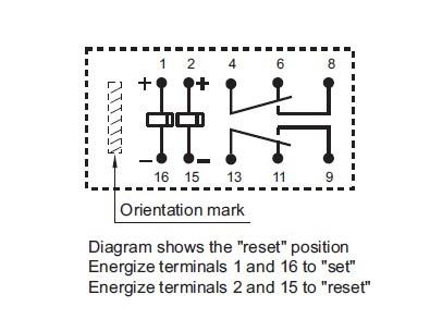
Using our Feather Stacking Headers (http://adafru. Step 1: Pick a relay and a push button and connect the circuit shown below. Latching Relays (also called ‚Bistable‘ or ‚Keep‘ Relays) Magnetic Latching Relays: Two-coil Latching Relays Relaxed State (after Reset) • Battery Not Connected to Coil The diagram shows the relay in the relaxed state. Fixed Contact – Normally Open (NO): The NO contact is open (disconnected from COM) when the relay is not energized.Schlagwörter:Non Latching RelayDual Coil Latching RelayTE Connectivity With inductive loads, about half that. This means that when the power supply is interrupted, the relay will switch off. The connections of this circuit follow as; First, need to connect the relay with a DC supply & B1 push-button.Our relay logic guide helps demonstrate the best ways to connect NCD relay controllers in real-world control applications.A non-latching relay is a type of electrical relay that operates based on a continuous input signal.Non-latching relays are a type of electrical relay that operates based on a continuous input signal. This involves stripping away .The differences between a latching and non-latching relay are the following: 1.
We connect relay and push button as per figure. Whether switching, separating, amplifying, or multiplying: relay modules and solid-state relays perform many different tasks in industrial applications. Let’s check them one by one. Label the push-button B1.To latch the relay, the common pin and the corresponding NO pin of the relay are connected in parallel to the start switch, as shown in the circuit diagram.
- Restaurant bräustübl – restaurant bräustübl speisekarte
- Tierärztliche plattform tierschutz / bundestierärztekammer e.v | tierärzte plattform
- Lachs mit bandnudeln und curry-soße für den thermomix®: tagliatelle mit lachs thermomix
- Aladin sky atlas und simbad, aladin sky
- Ist slack sicher? wie man bei der zusammenarbeit sicher bleibt – slack zusammenarbeit
- Neurologe in salzwedel mit sprechzeiten.: altmark klinikum salzwedel neurologie
- Wohnung, mietwohnung in nordhorn – 2 3 zimmer wohnung in nordhorn zu mieten gesucht
- French cartoons for kids – best french cartoons