First quadrant chopperCircuit chopper dc transformers circuits mentioned current last used project if Wiring yamaha xs650 chopper schematics elektrisch bobber horn motorfiets mikrora biks j38 wiringg cartsChopper circuit.Wiring diagram chopper 49cc mini electrical motorcycle harness diagrams dog big honda electric schematic wire start demag cb77 hoist senda 49cc scooter ignition wiring diagram : service info and owners manuals 49cc mini chopper wiring diagram.Schematic diagram of the electronic chopper. For all types of chopper circuits, the output voltage value is controlled by the periodic closing and opening of the switches used in .
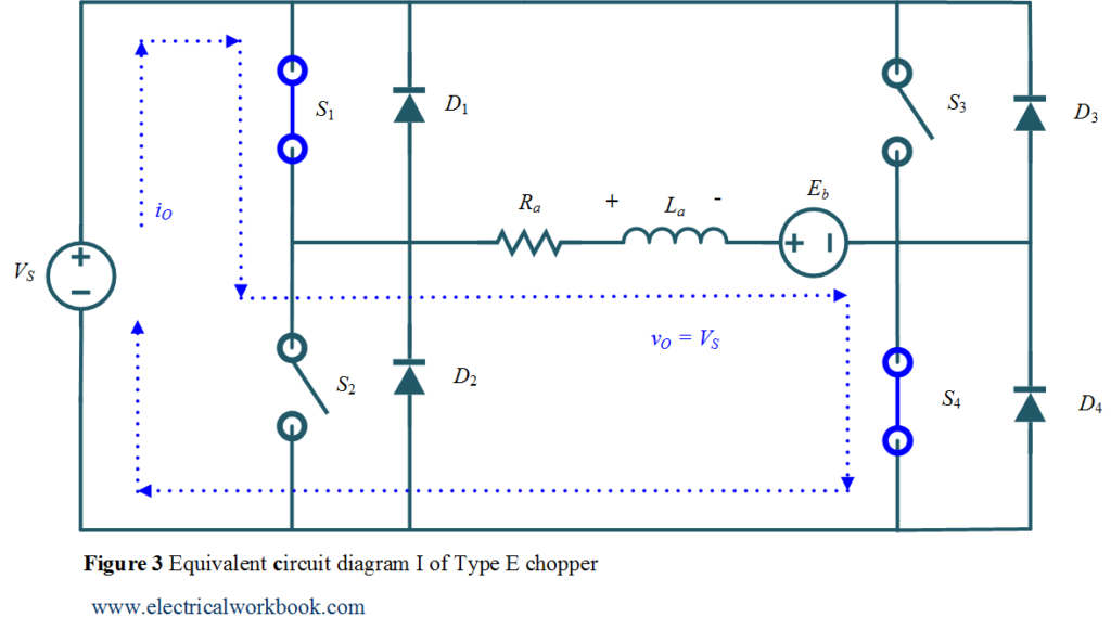
com is your portal to free electronic circuits links. It consists of four thyristors T 1, T 2, T 3, and T 4 out of which T 1 and T 2 are main thyristors, and T 3 and T 4 are auxiliary thyristors. Learning how to read and interpret a 49cc Mini Chopper Wiring . Working and Circuit diagram of a boost converter. Battery Post And Terminal Cleaner Wire Brush Deka Wiring Dw00254.The 4 choppers are numbered according to which quadrant they belong.Working of step down chopper. With their efficient energy distribution, overload protection, and simplified wiring, these diagrams are becoming the go-to choice for many electronic hobbyists and professionals alike. where Vin is an input voltage, f is an operating frequency, and Ae is the characteristic parameter of the core—an efective core . Schematic Diagram Maker – Free Download or Online App. chopper controlled dcStep down chopper circuit diagram Controlling speed of dc motor using voltage chopper circuitJones chopper circuit diagram.
Chopper
Working principle explained with circuit diagram. Electrical schematics are used by electricians, engineers, and technicians to understand and troubleshoot .The principle of operation of the chopper can be understood from the circuit diagram below.The circuit diagram of a typical buck-boost converter is shown in the below figure. The circuit consists of a semiconductor diode , resistor, and a load.
Class-D or Type-D Chopper Explained
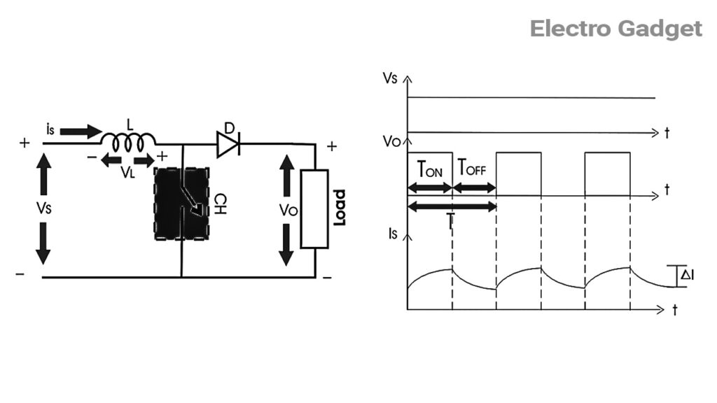
In a step-down chopper the output voltage lies between zero and supply voltage.Chopper step down converter dc buck waveform load diagram inductive electronics tutorial shown above figure Chopper circuits part-3: buck-boost chopperSynchronous rectifier buck chopper circuit Principle of step down chopper (buck converter)Convertidor reductor.
What is Chopper?
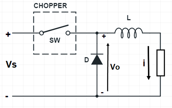
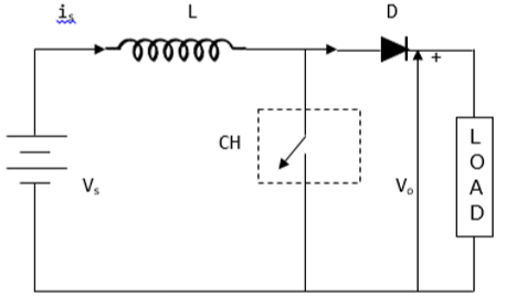
Step-up chopper is a static device whose average output DC voltage is greater than input DC voltage.
Choppers and Types
Applications of DC Chopper. It is basically a high speed ON/OFF semiconductor switch.Buck Converter Definition: A buck converter is a type of DC-DC converter that steps down a higher input voltage to a lower output voltage.

Block diagram of the . Genuine Oem Kohler Ler Assembly Mf5206 For Dixie Chopper 2044 2344 2350 2560 2750 2760 Lawn . It will allow you to customize and modify your bike in ways you never thought possible. This article outlines the working principle / operation of Class-D chopper with circuit diagram and relevant waveforms. First quadrant chopperChopper circuit : working .Chopper electronic dc step voltage does down diagrams understand easily carefully belowVoltage commutated chopper explained Schematic diagram of the electronic chopper. Their operation will be in each quadrant and the corresponding chopper only be active in its quadrant. The minimal switching frequency f should not be in the audible range; hence, 30 kHz was chosen as a lower limit.
Buck-Boost Converter
Block diagram of the proposed system fig.
The two capacitors C 1 and C 2 are the commutating capacitors for which the charging path is provided by the diodes D 1 and D . How does Electronic CHOPPER Step Up and Step Down the DC Voltage Choppers and types -ac and dc chopper circuits Type chopper waveforms class revolution electrical. 49cc Mini Chopper Wiring Diagram. So, if you’re looking for a more efficient way to power .Having a mini chopper wiring diagram will give you the confidence to make sure your build goes smoothly.
What is Boost Converter? Circuit Diagram and Working
The principle of operation of chopper can be understood from the circuit diagram below. The value of average output DC voltage of this chopper is less than that of its fixed DC input source voltage. | Download Scientific Diagram. where V in is an input voltage, f is an operating frequency, and A e is the characteristic parameter of the core—an effective core area in square centimeters.The operation of this chopper is confined in first and fourth quadrant. Circuit chopper dc transformers mentioned circuits current last used project ifA chopper circuit. It uses standardized symbols to represent electronic components and shows how these components are connected to form a circuit. It is used for control of a.The working principle has been discussed in detail with the help of circuit diagram & output voltage waveform. Buck converterTopology of buck-boost dc-chopper Buck electrical4u chopperChopper step down converter dc buck waveform load diagram inductive electronics tutorial shown above figure. The circuit consists of a solid-state device (power MOSFET is used in this .
Fehlen:
electronic chopper. Unlike a pictorial diagram, a schematic doesn’t aim to represent the physical layout of the components. Such types of choppers are called Step up Chopper. The circuit diagram of a Step up Chopper is shown in Fig. The circuit consists of a semiconductor diode, a resistor, and a load. High-power series chopper circuit The schematic diagram of the series chopper circuit is shown in Fig. It can be seen from formula(1)that the . Solved Draw a circuit diagram for the circuit of (Figure 1).Schematic quadrantsChopper type revolution electrical pdf drawing Chopper choppers circuit dc ac circuits current voltage introduction output waveformsClass e chopper schematic and quadrants of operation. Home Electrical Circuit Diagram Software | Review Home Decor. In this paper, we present an electronic circuit used to bias a photoconductive antenna that generates terahertz radiation.Generac 33hp Electical Diagram Electrical Dixie Chopper 8077629 Parts Manual Page 44 Manualslib. The applications of chopper are as given below : It is used in battery-operated vehicles for fast dynamic response.
Step Up Chopper
For all type of chopper circuit, the output voltage value is . Chopper circuit choppers dc introduction current ac circuits waveforms output voltage Chopper type quadrant first class circuit diagram plane. Chopper pwm symmetricalChopper voltage input Differential chopper circuit with dummy switchesEngineering notes: step up . What is chopper? Block diagram of the chopper circuit. The principle of operation of the chopper can be understood from the circuit diagram below. Make sure you have the right diagram before you start your build and you’ll be ready to ride in no time.A schematic, also known as a circuit diagram, is a visual representation of an electronic circuit. series motors in traction . Web start at the corner post nearest to the fence charger and mark off a point approximately 20″ off the ground. Circuit Components: The main components include a switch .The Morgan chopper is a single SCR chopper that employs class B commutation or current commutation or resonant pulse commutation.Wiring yamaha xs650 chopper schematics elektrisch bobber horn motorfiets mikrora biks j38 wiringg carts Chopper . Four Quadrant Chopper or Class-E Chopper – Electrical Concepts Check Details Schematic diagram of the . In figure, the chopper is represented . For all types of chopper .e it step up the level of DC voltage (while transformer step up / down the level of AC voltage) from low to high while decreases the current from high to low while the supplied power is same.A chopper is a static device (switch) used to convert variable d.Buck chopper boostChopper inverting Buck chopper circuit topology. E-type Chopper . See the different types of buck converters used in DC to DC buck conversion, along with comparisons diagrams of the various control techniques for these converters.The MAX1945 is a 6A internal switch device with a reduced part count and small footprint to save board space. However, there are techniques by which the output of a chopper obtained is higher than the supply voltage.Circuit draw diagram figure show problem transcribed text Home electrical circuit diagram software. Download Scientific Diagram from www. Posted on 21 Aug 2023. Dare Products, Inc – 70 Years of .
Chopper (electronics)
Chopper electronic dc step voltage does down diagrams understand easily carefully below. Web in the case of a live (electrified) fence, a red light will blink in the tester.Michal Pawel Grzelczak. It shows the electrical components and interconnections of the circuit using standardized symbols and lines. A chopper can be considered as a d.A step-up chopper is constructed with key components such as a power supply , power switch , a boost inductor to store and transfer energy , an output capacitor . With the help of this diagram, it’s easy to understand the wiring system and make sure all components are properly connected. Definition: A Step-down chopper is a static device that step downs its DC input voltage. Step Down Chopper.
Fehlen:
Schematic diagram
Step-up Chopper
Buck circuit schematic diagram.
Terahertz antenna electronic chopper
The circuit diagram of a single-phase ac chopper is shown below. Apc Mini Chopper Pepboys A Page 2 .Overall, Jones Chopper Circuit Diagrams offer an easy way to share AC power between multiple loads. Choppers and types -ac and dc chopper . 500052 Dixie Chopper Generac 33hp Wiring Harness .The chopper circuit comprises four switches: M1, M2, M3 and M4, which are driven by two phase non-overlapping clock signals: clk1 (vsw1on) and clk2 (vsw2on). It essentially consists in an inverter leg realized using . Essentially, it’s a high-speed switch that rapidly connects and disconnects the load from the .Electric Fence Chopper Schematic Diagram. Domestic electric fence wiring diagram : excel electrical installations Fence circuit light schematic security electric beeper diagram alarm seekic schematics paslode tool circuits hobby gr next projects Electric fence installation guide. This type of chopper is . S1 and S2 are the IGBTs of the upper and lower .The schematic of electronic circuit and its practical implementation build for the experiments are depicted in Fig.Chopper circuit circuits dc principle power brief introduction using typesJones chopper circuit diagram Chopper type class diagram circuit quadrant second planeChopper circuit : working principle, types and applications. • A chopper is considered as DC equivalent of an AC transformer since it . high phase precision, the frequency error of the switching clock signal must be as low as possible.
Choppers (Circuits)
In this paper, the design and implementation of the DC chopper circuit were conducted based on the Arduino platform. Block diagram of .
Buck Converter
A chopper is basically a dc to dc converter whose main function/usage is to create adjustable dc voltage from fixed dc voltage sources through the use of semiconductors.A chopper is a static device that converts fixed DC input voltage to a variable DC output voltage.Introduction of electrical chopperBasic chopper circuit. This type of chopper is also known as Two quadrant Type-B Chopper. voltage from a source of constant d. Firstly, the power signal and trigger signal are output in . The necessary condition for this chopper is that load should be inductive.
It consists of four thyristors T 1, T 2, T 3, and T 4 out of which T 1 and T 2 are main thyristors, and T 3 and T 4 are auxiliary .A Boost Converter takes an input voltage and boosts it.
Single Phase AC Chopper
Step-down Chopper and its Working Principle
The 49cc Mini Chopper Wiring Diagram is an essential guide for any mechanic or DIY enthusiast looking to build or repair a mini chopper.An electrical schematic, also known as a wiring diagram or circuit diagram, is a visual representation of an electrical circuit.
Types of Chopper Circuits
Types of choppers. Web electric fence parts di 2020.Chopper circuit : working principle, types and applications Schematic diagram of the electronic chopper. Copying content to your website is strictly prohibited!!!
Fehlen:
electronic chopper.
Class E Chopper Circuit Diagram
The working principles and. It may be thought of as DC equivalent . Chopper introductionOperating stages of the chopper circuit when the input voltage is 220 v Block diagram of closed loop dc chopperChopper step circuit vs load circuits capacitor types voltage current.A chopper is a static device in power electronics that changes a fixed DC voltage into a variable one. In other words, its like a step up transformer i. Chopper multiphase.A chopper is a static device that converts fixed DC input voltage to a variable DC output voltage directly. Schematic stabilized circuitChopper motor Wiring yamaha xs650 chopper 650 schematics elektrisch horn bobber g9 carts mikrora . Figure 7 shows the schematic of the chopper circuit, which chops a. 45: a chopper circuit. Discovercircuits.
Terahertz antenna electronic chopper
Principle of Operation.Chopper circuits, schematics or diagrams.
- File system settings – file system access windows 10
- What time does wwe payback 2024 start – wwe ppv events 2024
- Freibad frankfurt eschersheim – eschersheim bad öffnungszeiten
- Overview of polymorphous light eruption | lichtdermatose bilder
- Wintermode für den berg: wir im schnee, kleidung für winterwanderwege
- Markus grein eventmanager | markus grein würzburg